What is the Bus Interface Unit (BIU) | BIU Queue and Registers?
 | BIU Queue and Registers?") |
| Bus Interface Unit (BIU) |
The Bus Interface Unit (BIU), its Queue (Q), and Registers:
The Bus Interface Unit (BIU):
Bus Interface Unit (BIU) is the main block in the internal structure of the microprocessor’s CPU which performs the functions of fetching the instructions and data which is required and executed by the Execution Unit (EU) which is another main block of the CPU.
Along with fetching the instructions and data the BIU also deals with all the bus operations, reading and writing operands for the memory, and also calculates the operations of memory operands. After fetching the instructions by the BIU they are transferred in the form of instruction bytes to the instruction queue. Hence, the BIU is also responsible for instruction queuing and the generation of addresses.
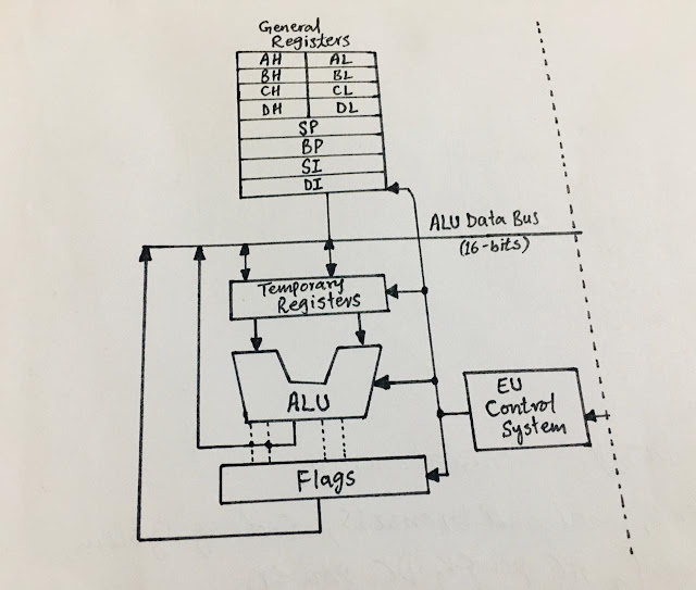
EU has no direct connections with the buses of the system so this connection is made possible with BIU and they both are connected with the system’s Internal Bus.
BIU-The Queue (Q):
The BIU contains Instruction Stream Queue (Q) along with the
Segment Registers, the Instruction Pointer, and the Address Summing Block.
Queue or queuing is actually a mechanism used by the BIU and
the queue BIU uses is the Instruction Stream Queue which is applied by the BIU
for a pipeline architecture. The queue allows a pre-fetch of instructions and
data up to 6 bytes of instruction code.
If the queue of BIU is not full, it contains room for two or
more bytes at least. Meanwhile, the EU can’t request BIU to execute the read or
write operands from the memory, and the BIU freely performs pre-fetching of the next sequential instructions separately in the memory.
When a byte is given to the input end of the queue, the FIFO
shifts that byte automatically to the empty location near the output end.
The code never gets held until and unless the EU is ready to
accept. So the instructions are temporarily waiting there for their turn in the
queue and it takes some time to fetch the instructions of the microcomputer’s
program and the time needed for the fetching is eliminated.
When the queue gets full the EU does not execute and
approach the data in memory then the BIU does not perform any bus operations
and that interval is mainly the no bus activity which takes place between a bus
operations and the state named Idle State.
Registers in BIU:
The BIU contains exactly four Segment Registers. Like the 8086 microprocessor is a 16-bit processor so in BIU the 16-bit contents of the
segment registers mainly point to the starting location of the segment
particularly.
The four segments of the BIU are:
Code Segment Register
(CS):
This register is usually paired with the Instruction Pointer
(IP) for the pointing of the next instruction to be loaded for the execution
into the instruction decoder. This is responsible for assigning the code of
any application and it has the base address unit of the segment.
Data Segment Register
(DS):
This register accesses the data used by any application in
anyone out of the four available segments containing the base address unit of
the segment.
Stack Segment
Register (SS):
This register has the base address of the stack segment. This
section of the memory stores addresses and data when a subprogram is executed.
Extra Segment
Register (ES):
Just similar to the DS, it has the base address of the segment
to access the data of an application.
It must be noted that the DS associates with SI registers,
and ES with DI registers.
There are two pointer registers that use the stack and they
are named as stack pointers and the combination of SS and SP, and the Base Pointer which points to the block of data element passed to any function.
The stack pointers SS and SP point to the value stored in the
memory.
All the four registers of 16-bit are connected as a
conjunction with the pointer and index registers to fetch and store the
instructions and data from the memory space.

Comments
Post a Comment
if you have any doubt, please let me know.