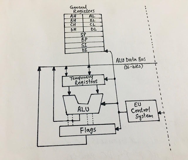
What is Execution Unit (EU), what does it do, and what are its belonging Registers?
 |
| Execution Unit (EU) |
Execution Unit (EU), it's functioning and belonging Registers:
As we discussed in our previous posts the Execution Unit(EU) and the Bus Interface Unit (BIU) are the interconnected main parts and blocks of the Central Processing Unit (CPU) of any 8086 microprocessor that deal respectively with the data and instructions in the memory with mutual collaboration.
Here we will discuss the functioning, the performances, the internal units, and the registers of the Execution Unit.
The Execution Unit (EU) decodes, executes, and reads the instructions fetched from the Bus Interface Unit (BIU) and it also generates control signals to the memory of the processor to manage the memory interface. It contains further different control units internally like Arithmetic Logic Unit (ALU), general registers, flag registers, pointers, and index registers. In modern CPUs, the execution units are usually pipelined.
ALU is the major
unit within the execution unit which plays a pivotal role in helping the
execution unit to execute and decode the instructions. The ALU deals with
arithmetic, logic, and shift operations which are required by any instruction,
for this purpose it uses a temporary operand register. ALU contains the data
processing logic and the instructions use the ALU to change the data but the
ALU does not store any data.
While executing the instructions the EU first checks the
status and control flags and updates them according to the results of executing
instructions. Hence, the fetching of instruction from BIU by the EU, decoding,
and executing them forms a cycle. All these processes are managed by the EU
control system.
The control unit of the EU performs the coordination of all
other units present in the processor, while the instruction decoder is
responsible for translation of the instructions fetched by the EU from the
memory.
Registers of the Execution Unit:
There are three kinds of registers in an Execution Unit:
General Registers, Pointer and Index register, and the Flag registers.
General registers
are activated for the temporary storage and manipulation of data and the
instructions.
There are further different types of general registers; accumulator register (based on two
8-bit registers AL and AH, and you can get a 16-bit AX register by combining the
AL and AH. Base register (also consists of two 8-bit registers BL and BH, and you
can get the register BX by combining the BL and BH. The BX register is used for
the pointing of data for based index or registers indirect addressing.
Another type of general register is the Counter 16-bit register CX which is generated by combining two
8-bit registers CL and CH and is used for the counter in string manipulation
and shifting or rotating of the instructions. Data 16-bit register combination of two 8-bit registers DL and DH
and used as a port number in input or output operations. It contains high-order
word of the initial or final number in 32-bit instruction multiplication and
division.
AX (AH, AL 8-bits) = Accumulator 16-bit
BX (BH, BL 8-bits) = Base 16-bit
CX (CH, CL 8-bits) = Count 16-bit
DX (DH, DL 8-bits) =Data 16-bit.
|
Register Purpose |
|
|
AX |
Word multiply and divide, word I/O |
|
AL |
Byte multiply and divide, byte I/O, decimal arithmetic |
|
AH |
Byte multiply and divide |
|
BX |
Stores address information |
|
CX |
String operation |
|
CL |
Shift and rotate variables |
|
DX |
Word multiply and divide, hold I/O address. |
Pointer and Index Registers:
The types of pointer and index register are Stack Pointer,
Base Pointer, Source Index Register, and Destination Index Register. Where the Stack Pointer (SP) and Base Pointer (BP) come under the
Pointer registers and the Source Index
(SI) and Destination Index (DI)
are categorized as the Index Registers.
Both the pointer registers SP and BP are used to access the
stack segment and the BP is used to access data on the stack also. While the
Index registers SI and DI are used for the pointing of memory locations in the
segment when there are string operations performed. SI is associated with DS
and the DI is associated with ES in the string operations.
Flag Registers of EU:
There are 9 active types of flag registers in the Execution
Unit, their names, abbreviations, and functions are described in the table
below:
|
Flag |
Purpose |
|
Carry Flag (CF) |
Holds carry after addition or borrow after subtraction, indicates
error conditions |
|
Parity Flag (PF) |
PF=0 odd parity, PF=1 even parity identifies even and odd parities |
|
Auxiliary Flag (AF) |
Holds carry (half-carry) after addition or borrow after subtraction
between bit positions 3 and 4 |
|
Zero Flag (ZF) |
Shows result of arithmetic or logic operation |
|
Sign Flag (SF) |
Holds result after arithmetic or logic instruction execution |
|
Trap Flag (TF) |
Enables trapping by on-chip debugging feature |
|
Interrupt Flag (IF) |
Controls operation of interrupt request |
|
Direction Flag (DF) |
Selects increment or decrement mode for DI or SI registers during
string instructions |
|
Overflow Flag (OF) |
Indicates overflow when signed numbers are added or subtracted |
The Flag registers are 16-bit in 8086 EU where 9 out of the
16 are active flags and the remaining 7 are not yet defined. The flag is actually a
flip flop that is responsible for the indication of conditions produced while
the execution of instructions by the EU.

Comments
Post a Comment
if you have any doubt, please let me know.